


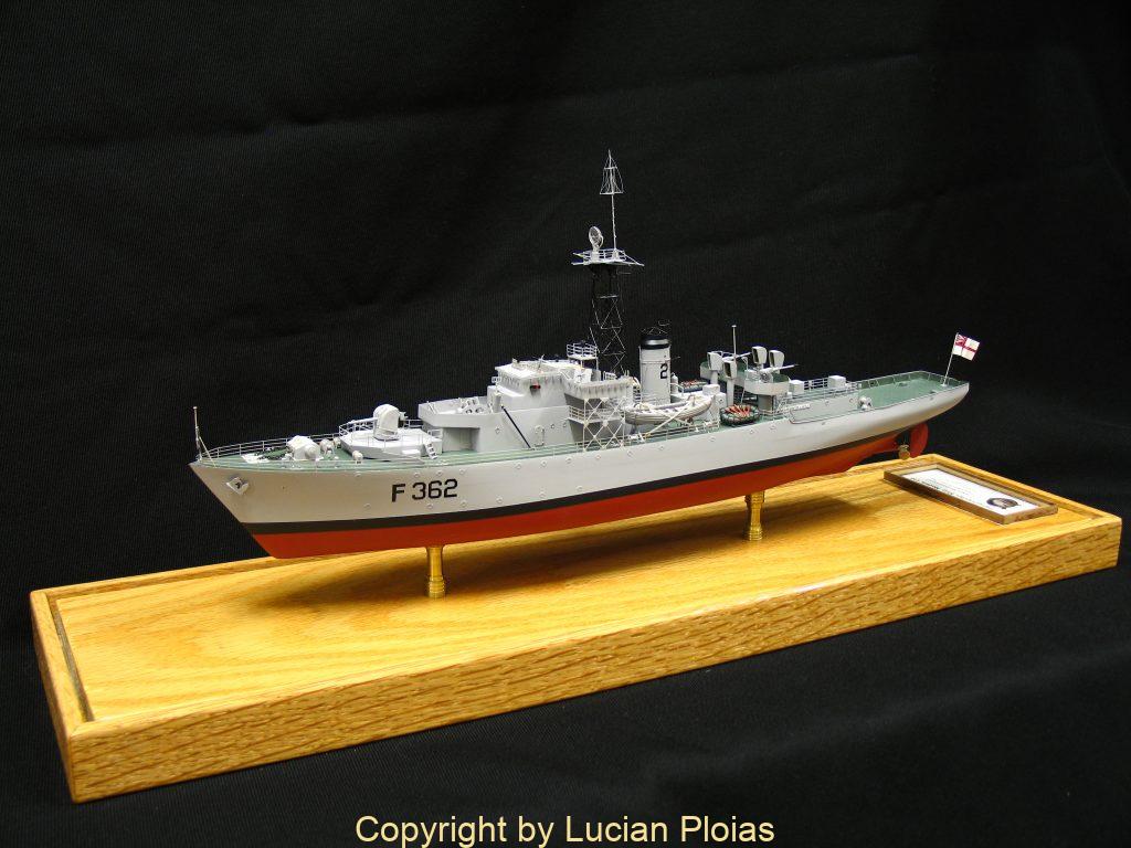
Modeling the Castle Class Corvette HMS “Portchester Castle”
The Ship
The Castle class Corvette was a natural successor to the “Flower” class. While the “Flower” was part of an emergency program to counter the menace of the German U-boat, “Castle” was a well planned and designed ship especially for the same task. These were far superior ships with better sea keeping capability, speed, armament and crew living conditions.
HMS “Portchester Castle” was built by the Swan Hunter & Wigham Richardson Ltd. at Wallsend on Tyne. She was laid down on the 17th of march, launched on 21st of June and completed on 8th of November 1943. On the 25th of December 1943 she was allocated to the Western Approaches Command, based at Londonderry, until the end of the war. On 9th of September 1944, HMS “Portchester Castle” teaming with HMS “ Helmsdale” depth charged and sank U 484 off the NW of Ireland coast, then on 11th of November she sunk one more enemy submarine the U 1200 off Cape Clear, south of Ireland. After more than one year of Atlantic service in January 1945 she took a 12 weeks long refit after that seeing two more months of action before the war end escorting surrendered German U-boats from their bases in Norway. From July 1945 up to the end of the year she was allocated as an Air Sea rescue vessel for the African Western Command. While serving in this duty she took part in the sinking of the steam ship “Edinburgh Castle” built in 1910. Her return to England being impractical she was towed off Freetown Sierra Leone and sunk with gunfire. Following year she served similar duties in Gibraltar and then she was laid up in 1946. In April 1951 she was prepared for service and after commissioning on 15th May was allocated to the 2nd Training Squadron, based at Portland, for anti-submarine warfare and general seamanship training. In 1952 she was chosen to take part in the Cruel Sea movie as a fictional HMS Saltash Castle and in 1956 while being laid up in reserve she is seen in an other World War 2 movie The man who never was. 1958 put an end to her career when she is towed to Troon for scraping.
HMS “Portchester Castle” specifications:
| Class and type: | Castle-class corvette |
| Displacement: | 1,060 tons , full load 1580 tons |
| Length over all Length between perpendiculars | 252′ (76.8 m) 225′ (68.6 m) |
| Beam: | 36’8” (11.18 m) |
| Draught (mean) Draught (max) | 13’6” (4.1 m) 15’9” (4.8 m) |
| Installed power: Fuel: | 2,880 IHP (2.14 MW) one 4 cylinder triple expansion steam engine, two Admiralty three drum type boilers 480 tons |
| Propulsion: | Single screw |
| Speed: | 18.5 knots |
| Range: | 9,500 nautical miles at 10 knots |
| Complement: | 90 (peace), 130(war) |
| Sensors and electronic systems: | Type 272 radar Type 144Q sonar Type 147B sonar |
| Armament: | One 4-inch Quick Firing Mk.XIX High Angle/Low Angle combined air/surface gun One Squid Anti-submarine mortar One depth charge rail, 15 depth charges Two 40 mm Bofors single anti-aircraft cannon Two 20 mm Oerlikon single anti-aircraft cannon |
The Model
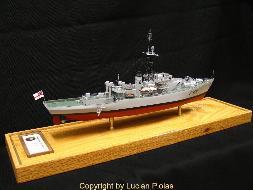
This was my second naval model built to 1:200 scale. Entirely built from scratch it has a length of 384mm, a beam of 55.9mm and a drought of 24mm. I followed detailed plans of the ship drawn by the late Norman A. Ough in 1955 while the ship was still in existence. This class of ships had graceful lines, so the hull (built on the bread and butter system) required 7 lifts, each 4.2mm thick with the exception of the top lift which was 9.5mm. For larger models I use either plank on bulkhead or plank on frames methods, but for such a small model bread and butter was a fast and precise method of generating the hull. I know for most of the experienced modelers this method is an old story, I would like to share with you how I did it in this particular case. The model being destined for display only the lifts were left solid with no empty space being necessary inside the hull. After making cardboard
templates for the outlines of each lift, I transferred these outlines to the timber. I milled my timber from a well seasoned plank of fine grained yellow cedar. This wood is an excellent material for planking hulls for models as well as for real wooden boats. The lifts were cut about 2-3 mm larger than outlines and assembled with screws into a rough hull block. Bow section and the stern are also roughly cut and then the entire hull is shaped using files, rasp, plane, scrapers and basically anything that can remove the excess wood and leave a nice shaped hull. When this stage was done, I made a temporary stand out of two 6mm dowels inserted into the hull bottom and a plywood base. This is important for the next step which is coating of the hull with an epoxy filler and this stand is use to keep the hull upright. I used West System epoxy resin with a slow cure hardener and 410 microlight filler. This filler is a powder like substance which mixes with the resin. I add small quantities of filler to resin while mixing it with a stick until I reach a mayo like viscosity. Before I coat the hull with this filler I apply two coats of CPES (clear penetrating epoxy sealer) which will seal the wood and will make the filler to better adhere to the hull. When this is set I sand using 220 grit sand paper and apply a second coat. At this point I made the bulwark on the aft part of the ship as well as the checkered steel upper deck and forecastle deck. These were made from 0.2mm brass sheet and epoxied to the wooden hull. A third coat of epoxy filler was then applied and after that final sanding using 600 Grit wet sand paper. Now the hull is ready to get her first coat of primer. After this coat a final check was done to spot any hidden imperfections and correct them. For painting I used a Paasche airbrush and acrylic flat paints.
At this stage, I find it expedient to mount the finished hull permanently on her brass pedestals and base board. I turned on my lathe two brass pedestals and I mounted these on a nice piece of oak as model base. The hull was secured with wood screws to this base.
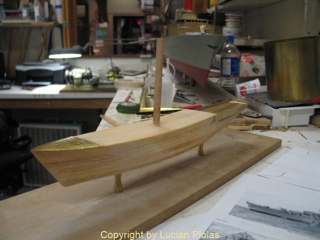
Hull ready to be painted
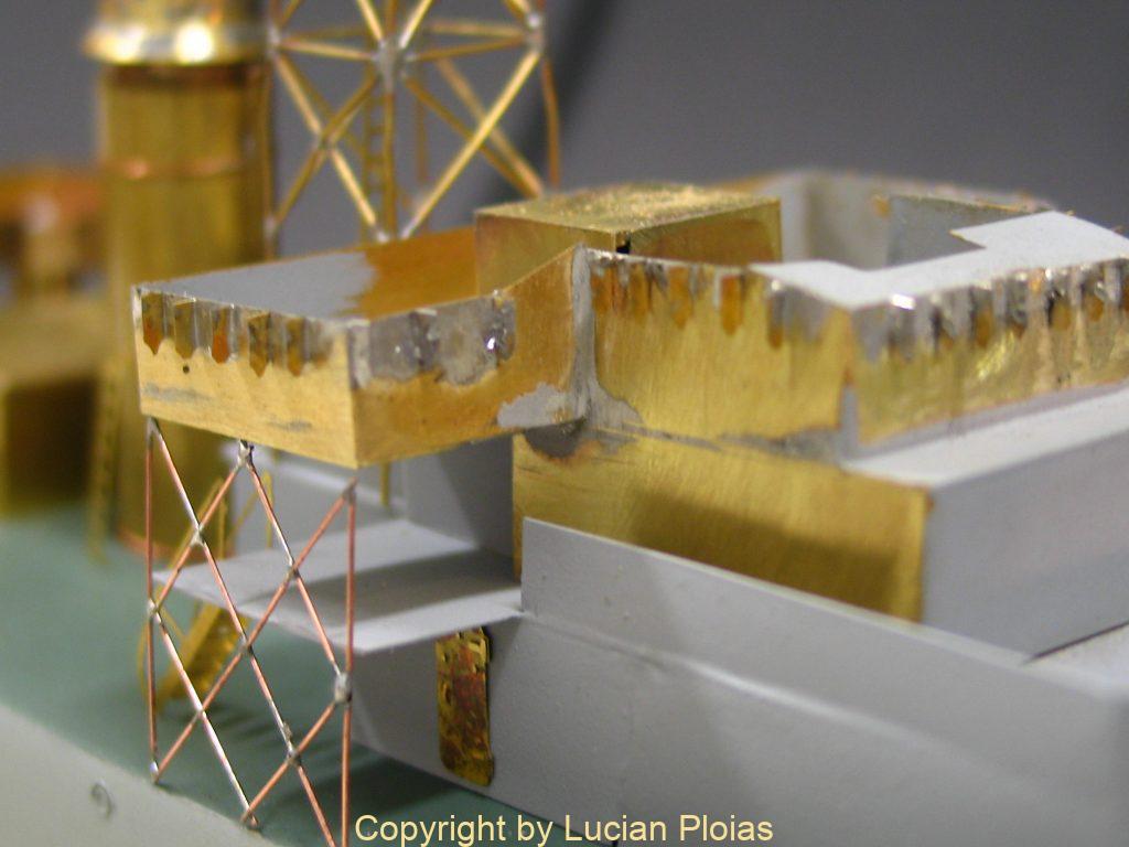
From this stage on, the only material used to construct the super structures, armament, masts and all other fittings with the exception of the ship boats was brass. One of its main qualities is that it has a smooth surface which doesn’t need to be filled, just a quick sanding with fine sand paper and is ready for painting. Only a few tools are needed: a vise, anvil, a scorer which can be ground from an old hacksaw blade, tin snips and very important a ball-peen hammer. Soldered joints must be cleaned and washed with water to clean up flux residue. Soldering in itself is not such a hard job. The parts to be joined must be well prepared before soldering. I use a 60W soldering iron and a butane torch. Before soldering I make sure that all the parts fit well together and I use only wooden clamps to keep them tight. If the parts to be soldered are too large for my iron I use the butane torch to preheat them.
I started with the 4”gun platform and then with the lower bridge area. I made cardboard templates from the drawings for each side of these parts. Then I drew on the brass sheet the unfolded shape of each part. I cut the shape using the scorer (which is used to mark off breaks or bending points in the metal much as a glass cutter does in glass and is very accurate and clean compared with cutting with scissors), or a fret saw with a special blade for brass. I used a flat nose pliers to bend to various angles and then soldered the joints. For the Bofors guns platform the two cylindrical columns were turned on the lathe. The platform was soldered on top of them.
On a 20th century warship there is always a multitude of metal structures built from angle iron, T or I bars these can be made using the scorer in combination with a straight edge resulting in a sharp clean groove along the metal which will bend allowing for clean breaks or bending for the formation of these profiles. T bars can be formed by soldering together angle bars.
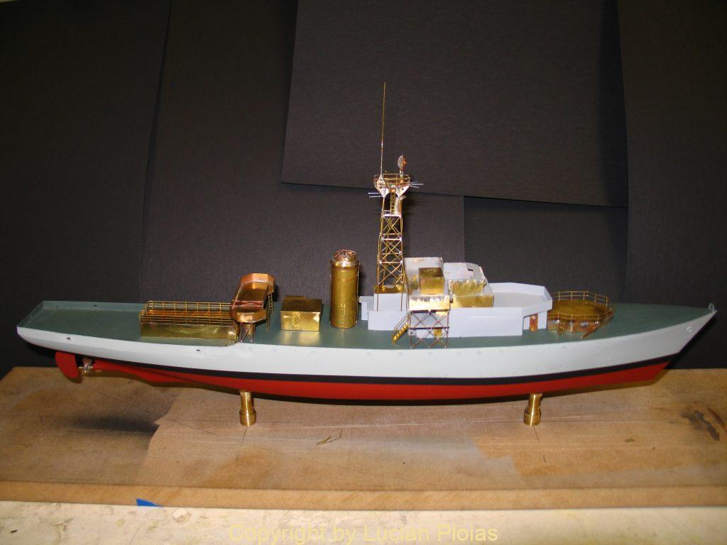
Hull still on a temporary stand showing brass superstructures
HMS “Portchester Castle” had a heavy lattice type fore mast with a dish antenna for the type 277 radar topped by the famous HF-DF aerial. This complex structure was modeled using 0.5mm brass round bar,
soldered on a wooden jig. Crow’s nest was made from a brass tubing cut to shape, radar dish antenna was made from a copper ring soldered on a piece of brass mesh previously formed to a hemispheric shape.. HF DF aerial was a bit more challenging due its size 10mm total height. Aerial wires 0.07mm were soldered to the frame for which I used copper wire 0.15 mm.
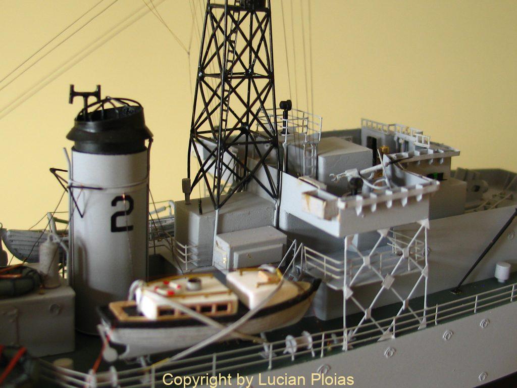
Thin brass sheet was also used to make the funnel, being fitted around an elliptic shaped wooden dowel. The funnel cage was soldered up from copper wire and fitted to the shaped hood. The entire assembly was given two coats of primer before it was painted. The funnel hood with its cage were painted flat black.
One interesting feature of this ship is the boiler room cowl ventilators shape. On most ships these were curved elliptical shaped, but on this and few other successive ships of this class these were of a more simpler shape being of a rectangular cross sectional shape. Based on information gathered from a photograph showing the forward set of these vents, I made them using brass rectangular tubing filed to the right shape and then soldered on a round brass tubing. The mushroom vents of various sizes found everywhere on the ship as well as the vent trunks in wall of superstructures were made from soldering round or rectangular brass tubing.
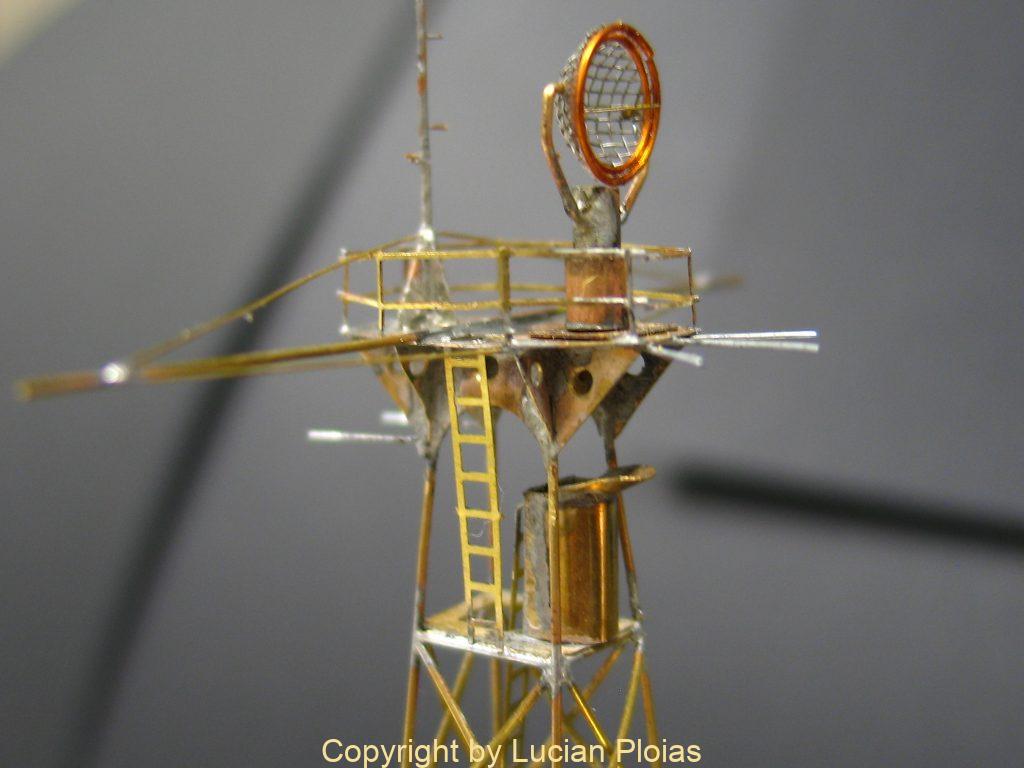
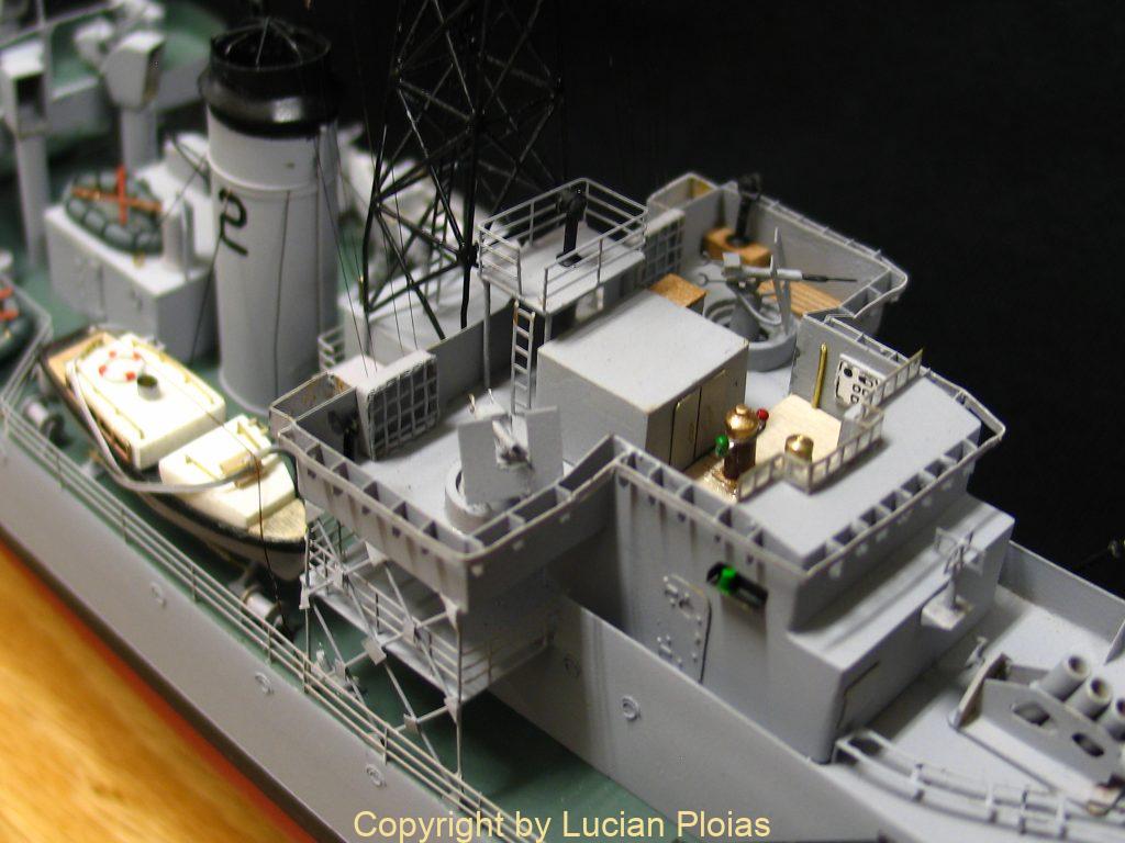
Radar platform and bridge structures
I am lucky enough to be in possession of the complete drawings set of Royal Navy warship’s details by Norman Ough as they appeared in Model Maker magazine during the 50’s and 60’s. The wealth of information found on these drawings is remarkable and a must for every model maker who is willing to get as much accurate detail on his model as possible.
The main armament on this ship consisted of one 4” H/A Mk XIX naval gun. Following Norman Ough detailed drawings I could get all dimensions for the many parts that were visible outside the turret. The barrel was turned on the lathe from a brass rod, the gun base plate and the two side plates that receive the trunions were made also from soldered brass. The turret sighting hoods were cut and bent from .3 brass sheet and then soldered on the shield. The 40mm Bofors and 20mm Oerlikon guns were made following the same procedures and also from brass material.
Depth charge mortar or the Squid consisted of a rectangular base with reinforcements gussets around it and three barrels mounted on a 30 degrees angle. A servo motor is placed on the fore part and a gear with a flying wheel on the aft part. The whole assembly is placed on the lower bridge platform one foot to port of centre line and this was also made of brass.
I tried to the best of my abilities to add as much detail to the open bridge, like gyro repeater, flag lockers, compass binnacle, voice pipes etc. Also the venturi shield was made by soldering it to the bridge sides.
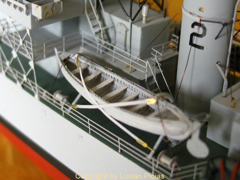
25′ motor boat and 27′ whaler in their quadrantal davits
Guard rails were photo etched and installed along the hull into holes which were drilled before paint was applied avoiding in this way a whole lot of trouble.
HMS “Portchester Castle” carried on board a 25′ motor boat, a 27′ navy whaler, a 16′ dinghy, two 12′ and one 10′ Carley floats.
The 27′ whaler reduced to 1:200 scale is only 42mm in length. This was planked (clinker) on a wood former using paper “planks” glued on paper ribs. There are 14 strakes from keel to gunwale on each side. The top plank which carries the rubbing strike is broader than the others. After the planking was done the shell was removed from the wooden plug and stem, keel and stern post was added. Also ruder, thwarts, gratings, oars and other specific equipment was added. Everything was painted flat grey and installed on its quadrantal davits. The 25′ motor boat was also clinker planked with paper “planks” this time on a solid piece of wood without the need of removing the shell from it. This boat has a small cabin with four brass ports on either side and a small hatch inside the forward canopy which were painted white. Hull was grey with black rubing strike and then installed on standard quadrantal davits.
The Carley floats were tackled next. I made these from brass rod bended to shape and then soldered a bottom out of a thin brass sheet. After that I paint them with flat dark green and installed a wooden grating and four oars for each float.
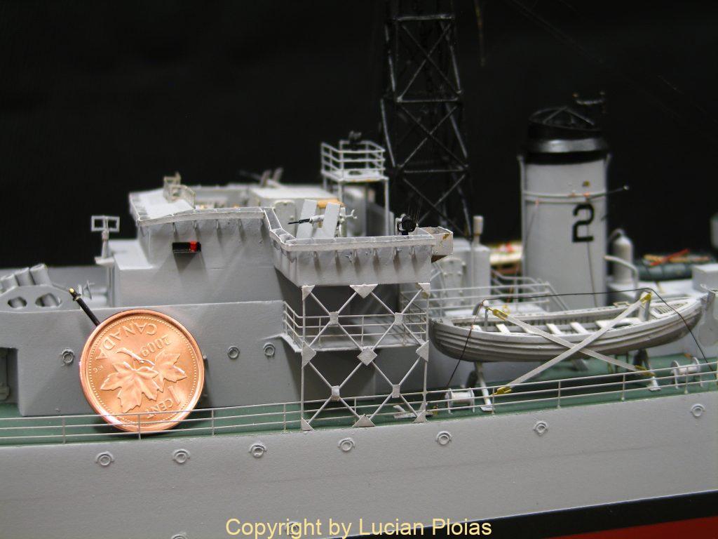
Upper bridge and port side views. Note the one cent coin is 19mm in diameter
In my opinion rigging is probably the most challenging item to model for a modern warship at such a small scale. The multitude of lines used for the funnel and masts stays, aerials as well as signal halliards which all are secured with shackles and other hardware are a real nightmare to make in such a way that they look as real as possible. The main mast stays were made using 0.2mm copper wire while for the wireless aerial I used copper wire 0.03mm from an old speaker transformer. All these lines were blackened with a black felt pen after installation.
This was my second naval model built at 1:200 scale, first one being a model of the River Class frigate HMCS “Kirkland Lake”. Working on a commission base only, usually my clients dictates the construction scale and at first I was challenged by the small size of these models but there are some advantages in working small scale. One of them is the little space needed to perform the work, everything can be made from scracth, and when is completed it will need an even smaller space for display. In conclusion according to my time log, I spent 1070 hours building this model of the HMS “Portchester castle”
References:
Norman Ough plan of HMS “Heddington Castle”
Norman Ough – Warships details series – Model Maker 1950’s 1960’s
Ken Macpherson – Frigates of the Royal Canadian Navy 1943-1974
A few words about the builder:
I am a professional model maker activating in Vancouver, British Columbia. Since 1996, I manage the Vancouver Maritime Museum model shop, where I build or restore ship models on commission for a large variety of clients. I was born and educated in Romania, I graduate Mechanical Engineering in 1991. More information can be found on my web site at www.transylvanian.com